Engineers often struggle to translate raw datasheet numbers into real-world circuit performance, especially for precision components like the MIC2333T-E. This guide cuts through the technical jargon to decode the MIC2333T-E datasheet, focusing on the key specs that matter most and the performance metrics that define its reliability in high-precision applications. By understanding these critical parameters, you can optimize your design for stability and efficiency from day one.
Understanding the Core Architecture of the MIC2333T-E
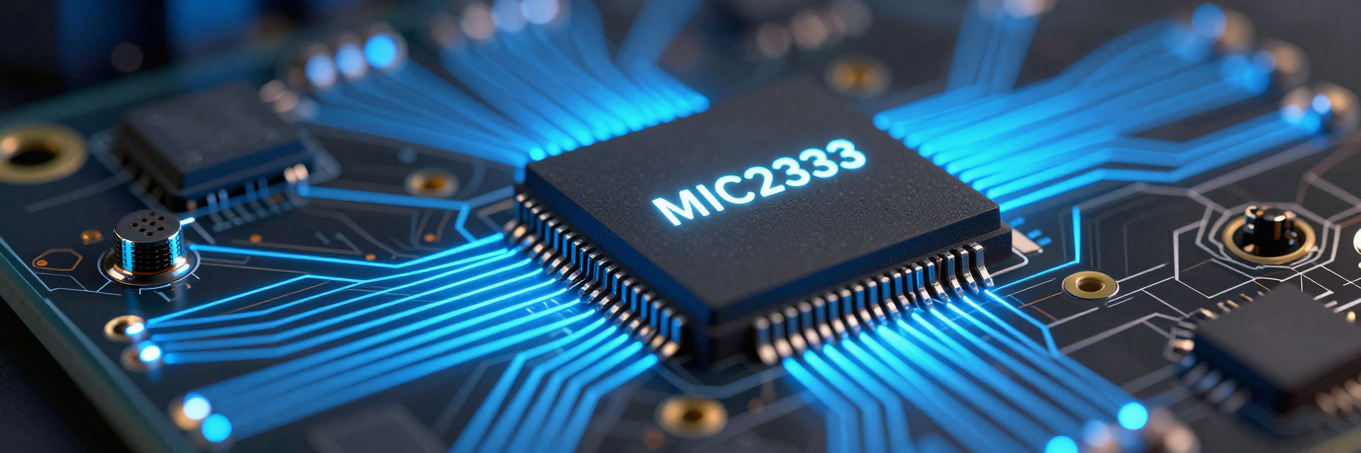
You need to grasp the internal structure before analyzing specific electrical values. The device operates on a specialized topology designed to eliminate common analog errors.
Zero-Drift Topology Explained
The MIC2333T-E utilizes a zero-drift architecture, which is crucial for maintaining accuracy over time. Unlike traditional amplifiers that suffer from input offset voltage drift due to temperature changes, this topology employs chopper stabilization techniques. You should understand that this method effectively cancels out low-frequency noise and DC offset errors. Consequently, the amplifier delivers near-perfect linearity even in sensitive measurement circuits where microvolt-level precision is required.
Dual vs. Single Channel Configurations
This component is available in both single and dual channel variants, offering flexibility in board space utilization. For dense instrumentation designs, the dual-channel version reduces bill-of-materials costs and footprint significantly. When selecting between configurations, consider your signal routing complexity. Dual channels allow for differential signal processing within a single package, minimizing inter-channel crosstalk if proper layout practices are followed. This integration simplifies power management by sharing supply rails across channels.
Decoding Critical Electrical Specifications
| Parameter | Typical Value | Impact on Design |
|---|---|---|
| Input Offset Voltage | < 5 µV | Minimizes calibration needs |
| Offset Drift | Nanovolts / °C | Ensures thermal stability |
| Gain Bandwidth Product | ~300 kHz | Limits high-speed response |
| Noise Density | < 10 nV/√Hz | Critical for low-SNR apps |
Now that you understand the architecture, let’s examine the hard numbers that dictate circuit behavior under load.
Input Offset Voltage and Drift Analysis
The input offset voltage is typically less than 5 µV, representing a standout feature in its class. More importantly, the offset drift is exceptionally low, often measured in nanovolts per degree Celsius. This metric ensures that your calibration remains stable across varying environmental conditions. In practical terms, you can trust this specification when designing sensor interfaces where ambient temperatures fluctuate. The tight distribution of offset voltage means minimal unit-to-unit variation, reducing the need for post-manufacturing trimming procedures.
Gain Bandwidth Product (GBP) and Slew Rate Limits
With a Gain Bandwidth Product of approximately 300 kHz, this amplifier suits low-frequency precision tasks rather than high-speed data acquisition. You must align your closed-loop gain with this GBP limit to ensure adequate phase margin. The slew rate, while modest, is sufficient for slowly changing signals typical in thermocouple or strain gauge applications. Attempting to drive fast transient signals may result in distortion; therefore, prioritize stability over speed when configuring feedback networks.
Performance Metrics Under Real-World Conditions
Datasheet values assume ideal conditions. Here is how the MIC2333T-E behaves in actual operational environments.
Noise Density and Long-Term Stability Data
The input-referred noise density is remarkably low, often below 10 nV/√Hz at higher frequencies due to chopping. However, be aware of the "1/f" corner frequency, where noise rises slightly at very low frequencies. Despite this, long-term stability remains excellent because the chopping mechanism continuously corrects for drift. Your design benefits from consistent output readings over months or years, making it ideal for industrial monitoring systems requiring minimal maintenance intervals.
Power Supply Rejection Ratio (PSRR) Impact
A high PSRR rating ensures that power supply ripple does not contaminate the output signal. The MIC2333T-E maintains strong rejection across audio and sub-audio frequencies. In noisy industrial environments, this characteristic protects your sensitive measurements from ground loops and switching regulator interference. You should still employ local decoupling capacitors, but the inherent PSRR provides a robust first line of defense against supply-induced errors.
Thermal Management and Operating Range Constraints
Temperature effects are the primary enemy of precision analog design. This section addresses how the device handles thermal stress.
Extended Temperature Grade (-40°C to +125°C) Behavior
The extended temperature grade guarantees specified performance across a wide range, from -40°C to +125°C. Within this envelope, key parameters such as bias current and offset voltage remain predictable. You can confidently deploy this component in outdoor sensors or automotive applications without derating concerns. The packaging materials are chosen to withstand thermal cycling, preventing bond wire fatigue or delamination issues that plague cheaper alternatives.
Quiescent Current Optimization Strategies
Quiescent current consumption is relatively low, supporting battery-powered devices. While precise values depend on the supply voltage, you should expect efficient operation suitable for portable instrumentation. To further optimize power, minimize unnecessary loading on the output stage. Since the chopping circuit consumes static power, disabling unused channels in multi-channel setups helps reduce total system drain, extending battery life in field-deployable units.
Design Implementation Best Practices
Knowing the specs is only half the battle; implementation determines final success.
PCB Layout Guidelines for Precision Amplifiers
Proper PCB layout is non-negotiable for achieving datasheet-level performance. Keep feedback traces short and direct to avoid picking up parasitic capacitance. Use solid ground planes beneath the amplifier to provide a low-impedance return path. Separation of digital and analog grounds prevents noise coupling into the sensitive input nodes. Additionally, place decoupling capacitors as close as possible to the power pins to suppress high-frequency transients effectively.
Component Selection for Input Filtering
Selecting appropriate input filters complements the amplifier’s bandwidth limitations. Small-value resistors and capacitors form RC filters that attenuate high-frequency noise before it reaches the input. Ensure that filter impedance does not degrade the source driving capability. For optimal results, use low-leakage capacitors to prevent additional offset errors. This passive filtering strategy enhances the signal-to-noise ratio without introducing active components that might add their own drift characteristics.
Summary
- Mastering the MIC2333T-E datasheet requires interpreting how key specs interact under load.
- Prioritize performance metrics like offset drift and PSRR for robust, noise-free operation.
- Use decoded insights to accelerate your next precision analog design successfully.
Frequently Asked Questions
What makes the MIC2333T-E suitable for precision applications?
Its zero-drift topology eliminates offset voltage drift, ensuring stable measurements over time. Low noise density and high PSRR further protect signal integrity in noisy environments.
How does temperature affect the MIC2333T-E performance?
The extended temperature grade maintains specified parameters from -40°C to +125°C. Minimal drift ensures reliability in harsh industrial or automotive conditions without significant derating.
Can I use the MIC2333T-E for high-speed signal processing?
No, its 300 kHz GBP limits it to low-frequency applications. It excels in slow-varying signals like sensor interfaces but is unsuitable for fast data acquisition tasks.
Why is proper PCB layout critical for this amplifier?
Proper layout prevents parasitic capacitance and noise coupling. Keeping feedback traces short and using solid ground planes ensures the amplifier achieves its datasheet-level performance specifications.